Dual-Purpose Wings: My Key To Efficiency

Being someone who has researched and studied the aerodynamic devices on an aircraft, I have always wondered about the use of aerodynamic devices from two perspectives. Specifically, I always wondered how the wings can be used for more than just producing lift. This was what sparked my idea of dual-purpose wings, devices that generate lift and help improve the efficiency of aircraft. While this may sound impossible or irrational, I believe this could change the way we look not just at wings, but all aerodynamic surfaces of an aircraft.

The fixed-wing, as I have previously discussed, is a marvellous invention that allows the efficient generation of lift while ensuring safety and comfort. The wing is a piece of innovation that may never be trumped, and I believe that it is not our goal to invent something better than the wing itself, but rather to make use of this invention the best we can. This is the principle behind the dual purpose wing, to use this invention as something more than just a lift-generating device.

The turbofan engine is another engineering marvel, and it is currently the most widely used method of powering an aircraft. The turbofan engine, as I have mentioned previously, works by taking in air at speed, accelerating the air by burning the oxygen using fuel, and propelling out air of higher mass at a higher velocity. The energy generated by an engine is dependent both on the velocity and mass difference of the air as it enters and leaves the engine. Since power is energy per unit time, the power generated is dependent on the mass of the air per unit time that flows through the engine, and this depends on the speed at which the engine can take in and let out the air. Hence, the more air that passes through the engine in a unit time, the higher the power generated by the engine.

To take in more air, engine manufacturers try to make the mouth of the engine as wide as possible. This allows the turbine to take in more air per unit time, thus producing more thrust. However, the higher the diameter, the higher the drag force, and there exists an optimal diameter for the engine. However, this has already been discussed and is not the purpose of this blog. Therefore, to increase the power generated without increasing the fuel usage, the mass of air entering the engine per unit time needs to be increased without increasing the diameter of the engine. This can be done using the dual-purpose wing.

What is the Dual-Purpose Wing:

The dual-purpose wing (DPW) is a wing that is attached to a region above and in front of the engine of the aircraft. For the purpose of explanation, let’s assume that the engine only takes in the air directly in front of it; that is to say, it only takes in the air that lies within a cylinder with a diameter equal to that of the engine and a length ‘x’ which the engine can suck in. This means that the air even millimetrically outside of the cylinder’s diameter cannot be taken in. In this scenario, the DPW is placed at a distance less than ‘x’ in front of the engine and is placed just above the diameter of the cylinder.

Capture.1PNG

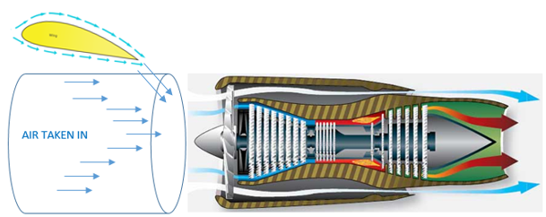
Figure-1: The DPW guiding air into the engine

In Figure-1 above, the yellow body in the DPW. The cylinder represents the region of air that is sucked in by the engine. As the diagram shows, the DPW is placed above the region of air and in front of the engine.

The DPW, like a regular wing, directs air downwards when air is passed over the wing. By this process, the DPW is able to generate lift. However, in serving its purpose as a wing, it indirectly helps the engine by guiding air downward. Without the DPW, the air that passes over the cylindrical space simply glides over the engine, but with the DPW, this air passes into the cylindrical region. By this process, the air that is directed downward enters the engine, providing an extra mass of air per unit time. The DPW allows more air to enter per unit time, and hence the mass of air that enters the engine per unit time is higher.

As previously mentioned, to increase the power generated by the engine, the mass per unit time that enters the engine needs to be higher. This is effectively accomplished by the DPW as it allows for the extra air that is normally wasted to enter the engine, thus producing more power while keeping the fuel usage the same. This not only allows for generation fo aerodynamic lift but also higher effective thrust.

FACTORS TO CONSIDER:

The higher the velocity of air flowing over the wing, the higher the lift generated by the wing. When enough air is passing over the wing and when the engine is running, the engine’s front turbine sucks in air. With the DPW, this includes the downwashed that comes from the DPW, and this hence increases the speed of air that flows over the DPW. when the velocity is higher, the lift generated by the DPW is higher, and the volume of air that is downwashed is higher. As a result of this, the DPW increases lift generated by using the engine while simultaneously increasing the power generated by the engine.

When the engine is at different operating levels, the distance ‘x’ could vary. As a result of this, the DPW may be ineffective at certain distances from the engine. This can be fixed by adding a movable mechanism to the GPW. This way, the position of the GPW can be varied by computer software that changes the GPW’s position relative to the engine’s power output. The DPW can be moved along the x-axis, that is to say, it can be moved to or away from the engine’s front face.

The DPW may be attached to the plane either on the side of the fuselage or through an extension of the wings. This depends on the camber of the DPW as well as the downwash it can produce. The DPW can be kept closer to the engine when the downwash is at a higher angle, while it is kept further away for a lower angle of downwash.

Additionally, the DPW’s width needs to be considered. It only needs to be as wide as the engine itself, and making it any longer could increase drag and reduce efficiency, thus proving to be counter-intuitive.

The DPW’s structural features also need to be considered. The material and the nature of the DPW (hollow/solid/semi-hollow) need to be considered. As the plane travels faster, the force on the DPWs is higher, and hence the DPW’s need to be higher in strength to combat this. Additionally, the DPW’s weight could affect the weight distribution of the aircraft. It could affect the centre of mass and pressure of the plane, causing a huge set of errors. These factors need to be considered to unlock the full capabilities of the DPW’s.

While the DPW’s work well in channelling air to the engines, they could face issues when it comes to interference with the wings. The air that is channelled to the engines (by the DPW) is the air that would, without the DPW, pass over the fixed-wing of the aircraft. When the air that is passed over the wing falls, the lift generated by the wing falls. This could lead to reduced lift, leaving the situation far worse than before. To prevent this disastrous issue, wind tunnels and thorough aerodynamic testing needs to be considered to find the optimal position of the DPW.

All in all, the DPW is just an idea that I had to improve the world of aircraft. While there is a multitude of factors to consider, this is not uncommon in the world of mechanics and aeronautics. I believe when engineering, planned, constructed and implemented, the DPW could be one of the vast ways to improve the efficiency of aircraft today. While DPWs may not be the next big thing, I am extremely happy with the idea that I came up with. I hope to think up such fascinating concepts and bring them to light in this blog!

Autogyro/Gyroplane

Autogyros, also known as gyroplanes or gyrocopters, are a type of aircraft that use an unpowered rotor to generate lift. The rotor is free to rotate and rotates automatically, hence the name autogyro. The aircraft only uses one propelled rotor to provide thrust to the autogyro. The thrust is then used to rotate the free rotor to generate lift. It is one of the concepts I read about recently and has caught my attention. I shall be further exploring this concept in this blog.

The autogyro was invented by Juan de la Cierva, a Spanish engineer. The autogyro is a unique invention and one that hugely interested me when I first heard about it. It was initially designed in the 1920s, with the design only improving over time. The autogyro has seen a lot of success in the past, with the machine having served in World War II. The key to commercial use of autogyros was seen in the Benson Gyrocopter. The simple design of the Benson Gyrocopter inspired innovation and showed the world the true simplicity of the autogyro.

maxresdefault.jpg

A gyroplane- Not the free rotor on the top and the fixed rotor behind

While the history of the autogyro may be interesting in its own, the working principle just blew my mind. From the image above, you can see the fixed propeller. This rotor is connected to a combustion engine that provides forward motion. For initial take-off, modern gyroplanes use the free rotor blade for propulsion. The free rotor is connected to the engine, and the speed of the autogyro is brought up to around 130rpm (revolutions per minute). This way, the autogyro is provided with both upward and forward motion similar to that of a fixed-wing aircraft.

When the autogyro has reached sufficient speed, it can reach a higher altitude and the free rotor can be disconnected from the engine. This way, the rotor is allowed to rotate by itself. Now the question arises:

HOW DOES THE ROTOR TURN AUTOMATICALLY?

To answer this question let’s assume the gyroplane is already in the air (after the engine has been disengaged from the rotor). The gyroplane has forward propulsion due to the back-mounted rotor. The blades of the gyroplane are angled in a specific manner as to partially face the incoming air due to the propulsion. This can be seen in the diagram.

Comparison_Gyro_1.jpg

Motion of Gyroplane

Notice that the blades of the gyroplane are angled such that the incoming air would hit the blades. This causes rotation of the blades of the gyroplane. When the blades rotate, a lift force is generated, pushing the gyroplane upward. It’s also important to note that the gyroplane is always moving downward with respect to the air around it. This means that the air is moving upward with respect to the blades. This causes the air to exert a force on the blades of the rotor. This causes the blades to rotate, again generating lift.

The use of moving air to rotate the rotor and generate lift has many advantages for the gyroplane. This includes providing stability at lower speeds. The moving rotor acts as a gyroscope, thus providing stability to the gyroplane. In addition to this, the gyroplane will descend safely and slowly if the forward propelling motor were to fail. If the motor were to fail, the forward velocity of the gyroplane would fall. As a result, the lift produced by the plane would fall, and the gyroplane would start to descend. As this happens, the air would move against the blades at a higher velocity. This would exert a higher force on the blade, increasing the lift again. However, due to the inefficiencies in rotation, the force exerted by the air wouldn’t be equal to the upward lift force. As a result, the gyroplane would fall downward at a low rate. Hence, the gyroplane would slowly descend downward at a slow rate until it reaches the ground. Due to this stability of the gyroplane, it is preferred by those who wish to fly small distances at a low speed.

The gyroplane concept was initially extremely difficult for me to grasp. However, after researching vastly by reading articles and watching videos, I managed to grasp this amazing concept. I hope to have effectively explained this concept to you, and I hope you enjoyed reading this article. I hope to build my own autogyro one day, and I’ll be sure to demonstrate my progress in this blog if I do. Thank you for reading, and I hope to see you again!


The fuel efficiency of an aircraft

There’s a huge misconception out there that planes are inefficient. With drastic figures out there, it’s understandable why this misconception exists. For instance, a B737-800 burns upto 2800 litre of fuel per hour. While it does seem inefficient at the surface, further exploration of the topic reveals that there’s nothing further from the truth.

Planes carry huge amounts of fly. Even smaller planes such as the A320 neo can carry upto 24,000 litres of fuel on a trip. This is an astounding amount, and leaves one wondering how much a larger aircraft would carry on a long-haul flight. Upon further exploration, we can decipher that the A320 has an efficiency of 0.67 mpg(miles per gallon) or 0.28 kmpl( kilometers per litre). The average car has an efficiency of 23.8 mpg, which is 35 times better than that of the a320. So far, the odds are against the A320, as these are appalling figures.

However, we need to take into consideration the number of passengers the A320 carries(154), while the average car carries only 5. By calculating the efficiency of the plane per person, we come to the conclusion that the plane has an efficiency of 107.4 mpg or 45.7 kmpl. Hence, the appalling efficiency of the plane is offset by the number of passengers it carries.

Since the invention of planes, they have gotten more and more efficient. The efficiency is undeniably increasing as both technology and awareness of the inefficiencies improve. Let us look into the statistics to observe this change in efficiency.

Model First flight Seats Fuel Burn Fuel efficiency per seat
Airbus A319 1995 124 2.93 kg/km (10.4 lb/mi) 2.95 L/100 km (80 mpg‑US)[57]
Airbus A319Neo 2015 136 2.4 kg/km (8.6 lb/mi) 1.93 L/100 km (122 mpg‑US)[26]
Airbus A320 1987 150 3.13 kg/km (11.1 lb/mi) 2.61 L/100 km (90 mpg‑US)[57]
Airbus A321-200 1996 180 3.61 kg/km (12.8 lb/mi) 2.5 L/100 km (94 mpg‑US)[57]
Airbus A330-200 1997 293 5.6 kg/km (19.8 lb/mi) 2.37 L/100 km (99 mpg‑US)[57]
Antonov An-148 (1190 nmi) 2004 89 2.75 kg/km (9.8 lb/mi) 3.86 L/100 km (60.9 mpg‑US)[32]
Antonov An-158 (1190 nmi) 2010 99 2.83 kg/km (10.0 lb/mi) 3.57 L/100 km (65.9 mpg‑US)[32]
Boeing 737-600 1998 110 2.77 kg/km (9.8 lb/mi) 3.15 L/100 km (75 mpg‑US)[47]
Boeing 737-700 1997 126 2.82 kg/km (10.0 lb/mi) 2.79 L/100 km (84 mpg‑US)[47]
Boeing 737-700 1997 128 2.8 kg/km (9.9 lb/mi) 2.71 L/100 km (87 mpg‑US)[57]
Boeing 737 MAX-7 2017 140 2.51 kg/km (8.91 lb/mi) 1.94 L/100 km (121 mpg‑US)[26]
Boeing 737-800 1997 162 3.17 kg/km (11.2 lb/mi) 2.44 L/100 km (96 mpg‑US)[47]
Boeing 737-800 1997 160 3.45 kg/km (12.23 lb/mi) 2.68 L/100 km (88 mpg‑US)[57]
Boeing 737-800W 1997 162 3.18 kg/km (11.3 lb/mi) 2.45 L/100 km (96 mpg‑US)[58]
Boeing 737 MAX-8 2017 162 2.71 kg/km (9.6 lb/mi) 2.04 L/100 km (115 mpg‑US)[58]
Boeing 737-900ER 2006 180 3.42 kg/km (12.1 lb/mi) 2.38 L/100 km (99 mpg‑US)[47]
Boeing 737-900ERW 2006 180 3.42 kg/km (12.1 lb/mi) 2.37 L/100 km (99 mpg‑US)[58]
Boeing 737 MAX-9 2017 180 2.91 kg/km (10.3 lb/mi) 2.02 L/100 km (116 mpg‑US)[58]
Boeing 757-200 1982 190 4.60 kg/km (16.33 lb/mi) 3.02 L/100 km (78 mpg‑US)[57]
Boeing 757-200 1982 200 4.16 kg/km (14.76 lb/mi) 2.59 L/100 km (90.8 mpg‑US)[48]
Boeing 757-300 1998 243 4.68 kg/km (16.62 lb/mi) 2.4 L/100 km (98 mpg‑US)[48]
Airbus A220-100 2013 125 2.28 kg/km (8.1 lb/mi) 2.28 L/100 km (103 mpg‑US)[50]
Airbus A220-300 2015 160 2.56 kg/km (9.08 lb/mi) 2.00 L/100 km (118 mpg‑US)[51]
Airbus A220-300 2015 135 2.30 kg/km (8.17 lb/mi) 1.85 L/100 km (127 mpg‑US)[26]
Quest Kodiak 2004 9 0.71 kg/km (2.52 lb/mi) 6.28 L/100 km (37.5 mpg‑US)[59]

The table above shows the efficiencies of multiple commercial aircraft. As we can see, the newer the plane, the higher the efficiency seems to be. An older plane like the A330(1997) has an efficiency of mpg, while the newer A220(2015) has an efficiency upto 127 mpg in the short range. This tremendous increase in efficiency only goes to show planes have improved over time.

This growth in efficiency can be pointed to the improvements in engines as well as increase in aerodynamic efficiency. Newer planes are starting to use more efficient engines as opposed to larger, more powerful engines. Boeing, in it’s newer 777-X series, is shifting from the 777-300ER’s GE90(the largest engines in commercial operation) to the GE-9X engines. Engine manufacturers such as GE, Rolls Royce, and CFM Leap have managed to improve overall efficiency without compromising too much on power.

The aerodynamic aspect of planes is also extremely important. It helps in reducing form drag and induced drag which are prominent factors leading to inefficiency. Boeing’s new 737 MAX(yes, the disastrous one) has the new and improved AT winglet, the most efficient winglet design. It improves efficiency by 12% by reducing induced drag.

Given the particular need for efficiency today, we can only hope that engineers are able to come up with more efficient ways to fly. Whether it be through the improvements in engines, aerodynamics, structures or a totally unrelated field, let’s all hope that we fly more efficiently tomorrow.


Thanks for reading this blog. If you liked the content, and seek to know more on planes, do subscribe to my blog to receive e-mail notifications every time I upload a blog. Follow aircraft_blogger on Instagram for updates and notifications on new content! I would appreciate your invaluable feedback, so please do leave your suggestions down in the comment section. This is Sushant Guha, and I’ll see you in the next blog!

Crash Chronicles #4 – Boeing 737 MAX 8! What went wrong?

I’m sure all of you have heard of the recent crashes of the Boeing 737 MAX-8. The first one of Lion Air, and the second one of Ethiopian Airlines, the planes have had similar circumstances, having crashed right after take-off, and both being technical failures. But, what happened wrong that killed the 346 passengers? This is the topic of today’s blog.

To understand the issue, we must first take a look at the engines of the plane. They are extremely efficient, but are larger and heavier. As a result, there were forced to be placed further front than before. This change yielded a 14% higher efficiency than before. This caused serious stalling threats as the nose of the plane was pitched up due to the awkward engine placement. This caused threats of stalling, which is where there is loss on the generation of lift by the wings. This causes the nose to be pushed further up, and the plane would, as a result, plummet down.

The 737 MAX has a system called the MCAS (maneuvering characteristics augmentation system). This system is meant to prevent the aircraft from stalling by pushing the nose down when necessary. The plane has two sensors to detect stalling. These are the angle of attack (AoA) sensors and are designed to provide inputs into the autopilot to adjust the angle of the nose in case of a stall situation. On the Boeing 737 MAX, however, the MCAS took inputs from only 1 sensor. Even if the inputs from both the sensors were different, they weren’t compared to check if one of them is faulty. This was the fatal mistake that lead to the downfall of both the planes.

On the day of the accidents, the one sensor from which the input was taken happened to be faulty. The input from the sensors lead the MCAS to believe the AoA of the plane was much higher than it was in reality. This lead the plane to automatically put the plane into a serious nose dive. The pilots, unfortunately could not overrule this MCAS, and as a result, lost their lives.

The combination of the input from only one sensor, and by chance the one sensor being faulty, sealed the fate of the passengers and crew of both planes. This is the reason the 737 MAX is now grounded. From the time of the crash, nearly all countries have grounded the plane as a result of the serious risk of running it. The grounding has caused massive issues for Boeing, as not only do they have to fix the issue as fast as possible, their reputation as an aircraft manufacturer has also been ruined. Many airlines have cancelled their orders of the 737 MAX, and some are looking to replace it with the A320-neo. This would end up being a huge loss to Boeing, and a massive gain for Airbus. The planes will continue to be grounded until the issue is resolved, and enough number of tests are run to prove the airplane as airworthy. Can Boeing come back from this major set back and continue to sell the 737 MAXs? Only time can tell.

Thanks for reading this blog. If you liked the content, and seek to know more on planes, do subscribe to my blog to receive e-mail notifications every time I upload a blog. Follow aircraft_blogger on instagram for updates and notifications on new content! I would appreciate your invaluable feedback, so please do leave your suggestions down in the comment section. This is Sushant Guha, and I’ll see you in the next blog!

Reverse Thrust

Many of you readers may have seen thrust reversers in action, others may be wondering what it is. As the name suggests, reverse thrust is just thrust in a reverse direction. Why would planes need this though? how does it work? and when is it used? This blog will address all these questions and will also give more information on the matter.

Image result for reverse thrust

Reverse Thrust In Action

Reverse thrust is a device that is used when landing to slow down the plane. It uses the power of the engine itself, and redirects the air in the opposing direction to effectively slow down the plane. As you can see in the picture above, the flaps on the side of the engine open up, and the air that goes into the engine is forced in th opposite direction. This creates a force that opposes the motion of the plane, thus slowing it down. Those who have read my blog on aircraft engines will know that 80% of the air that enters the engine moves around the outer shell of the engine, and only 20% of the air enters the combustion chamber. The thrust reversers work by controlling this 80% of air. Hence, it is extremely effective.

Reverse thrusters are used while landing to slow the plane down. The pilots use the reverse thrust along with the air brakes and the wheel brakes to slow the plane down. So, it is used when landing. Most of the time, however, the entire reverse thrust is not utilised by the pilots. Only when the runway is wet, or is very short, do the pilots use maximum reverse thrust. This is because the wheel brakes don’t work as well in wet conditions, so te reversers are need to compensate for this. When the runway is short, the aircraft may not be able to land in the given length without the stopping force of the reversers.

Newer reverse thrusters work by opening a slot (cascades) on the side of the engine and guiding the air out of the slot. The end result is the same as that of the one in the picture above, but it is more effective.

Image result for principles of glider flight

This diagram shows the working of the modern reverse thrusters

This modern-day reverse thruster may not be very visible, but is very effective all the same. Reverse thrusters weren’t always so compact though. In the olden days of the 737-100’s, reverse thrusters looked and worked very differently.

Image result for reverse thrust 737-100

Here the thrust reversers can be seen in action

The reversers consisted of two large conical flaps that would extend from the side of the engine and cover the output of the engine( Video of thrust reversers). This would push the entire exhaust of the engine in the opposite direction, thus slowing down the plane. Though it looked much cooler, it is not so common nowadays since the other methods are more efficient.

Now the question has to be asked. If thrust reversers really provide so much force, why can’t they be used for pushbacks instead of the pushback tractors? There are multiple reasons for this. If used for pushback, dust, debris and other particulate can enter the engine, thus damaging it. This could end up extremely bad for the engine, and may render it useless. Another problem is noise. It would be extremely noisy to use reversers for pushback. Even now, the reversers are used in idle position while landing to prevent too much noise, and airports discourage too much reverse use. This would end up being a disaster. The third problem would be costs. It would be very inefficient for thrusters to be used for every pushback. Due to high oil prices nowadays, this is unlikely to ever happen. The final, and maybe most important reason is the damage to the engine. The pushback would require high amounts of thrust for a short span of time. The engine, especially when not warmed up, could be damaged by the sudden increase in the thrust. If repeated for every takeoff, the engine would face high wear and tear.

So that’s all you need to know about the basics of thrust reversers. Thanks for reading this blog. If you liked the content, and seek to know more on planes, do subscribe to my blog to receive e-mail notifications every time I upload a blog. Follow aircraft_blogger on instagram for updates and notifications on new content! I would appreciate your invaluable feedback, so please do leave your suggestions down in the comment section. This is Sushant Guha, and I’ll see you in the next blog!

What Is Aspect Ratio?

There are many factors that are important in deciding the shape of a wing. It must be efficient in production of lift, light, structurally sound and must have enough space to hold enough jet fuel. Hence, engineers work tirelessly to make it as efficient as possible. This blog will talk about the most important aspect of the wing, the aspect ratio.

What is aspect ratio? It is the ratio of the span (length) of the wing to its chord (width). But first, to understand the importance of aspect ratio, we must understand the model of an ideal wing. An idol wing is one that generates maximum lift with minimal drag. Of course this is not exactly possible. This is because of induced drag, without which there cannot be any lift. This was discussed in one of my previous blogs, so do check it out to find out more about it.


Image result for aspect ratio of a wing


As mentioned, the induced drag of a wing cannot be eliminated, but it can be reduced without having a big effect on the lift generated by the wing. This can be done by adjusting the aspect ratio of the wing. Research shows that there is a small increase in the efficiency of the wing with an increase in the aspect ratio (higher length, shorter breadth). As the aspect ratio rises, the induced drag of the plane falls.

To understand this, we must look back at induced drag. Induced drag is generated when the air from beneath the wing flows from the lower pressure to the higher pressure above the wing. This form of drag is a result of lift, and cannot be eliminated. The flow of air from high to low pressure happens around the wingtips of the plane. This is explained in my “why winglets are necessary” blog. Now, imagine a wing with infinite wing span. There can be no induced drag since the air can’t flow up from under the wing. Hence, there would be no induced drag. Obviously, this cannot happen in real life, but we can still keep the wing span extremely high to try and reduce the induced drag. This is the exact way that a high aspect ratio makes the wing more efficient. This high efficiency is very important in aircraft that need to fly long distances, gliders and sailplanes. This explains why the wings of gliders are abnormally long.

Of course, this high aspect ratio comes with some disadvantages. The structural integrity of the wing is compromised. The wing is thus much heavier and less manoeuvrable. A plane with higher aspect ratio also takes up more space on the ground. These explain why we don’t normally see these high aspect ratios on commercial planes.


Due to all the factors given above, fighter jets have a very low aspect ratio of about 5 to 1. Sailplanes and gliders mentioned above, however, have an aspect ratio as high as 20 to 1. For a commercial plane, the aspect ratio of 6-10 to 1. Newer planes such as the 777X have an aspect ratio of 9, while the older Boeing 747 has an aspect ratio of 7.

Thanks for reading this blog. If you liked the content, and seek more of this similar content, do subscribe to my blog to receive e-mail notifications every time I upload a blog. Do subscribe to aircraft_blogger on instagram! This is Sushant Guha, and I’ll see you in the next blog.

The Unusual Tale Of The 757

When great airliners come to mind, you think of the 747, 737, A320 and maybe the A380. Few people think of the 757 as a massive success story which sold in the 10,000’s like the 737. And, they’re right, it didn’t. Merely 1050 of these planes were ever built. Why then are we talking about it? Because of a special twist in its story.

The Boeing 757 was first introduced on 1st Jan 1983 with the Eastern Airlines. It served well until Boeing stopped production in 2004, and though some 757’s are still in the air, most of them are extremely old and ready to visit the graveyard.  The 757 was introduced as a single isle, twin-engine aircraft that served as an extended 737 with higher capacity and longer range. It could carry up to 240 passengers to a range of about 6500 Km, and was intended as a carrier for short routes with high demand.

Now that we have the specifics out-of-the-way, we can begin the actual story. The 757 was built at a time when the  ETOPS rules were still present. These rules prevented any twin-engine plane from flying above 60 minutes away from an airport. This ruled out any trans-Atlantic flights for the 757, limiting it to domestic flights. This was the case in the US, where the main purpose of the 757 was to fly highly demanded short distance routes. When it released, it was far more efficient than any of it counterparts, and the original 757-200 had extremely high demand.

However, as time passed, the demand dropped and Boeing cut back on productions, until 2004, when they completely stopped the program. There were still a large number of 757’s in the air as they were still relatively new planes. From 2004 to 2007, there really isn’t much to say. It was a boring time frame as far as the 757 is concerned. As time went on, however, things changed.

The ETOPS rules were removed, and twin-engined planes were now allowed to cross large water bodies without any trouble. This changed the way airlines used the plane. With a formidable range and good passenger capacity, the 757 was the perfect plane to carry passengers internationally, a prospect which Boeing had not considered. This drastically changed the way people flew, since long-range flight was now efficient, affordable and very much possible with 2 engines. Due to the small size of the plane, airlines were able to fly it between smaller airports with less demand. This made a big impact on the market, making it easier for travel for tourists and businessmen alike.

Now comes the problem. They are getting old. Very old. With some aircraft due to retire, and some waiting for the impending doom, airlines have started to look for replacements. However, there are none. There is no plane of the same specification, with the same purpose and similar characteristics. This is one of Boeing’s biggest mistakes, as an efficient, more comfortable form of the plane would have extremely high demand to fill in for the older 757’s. Some argue that the 787 would fit the role, but it is far from the truth. It has a greater range, higher passenger capacity and hence cannot land at smaller airports which the 757 can handle. With too many seats, there would be empty places, and shorter routes under utilize the plane’s capacity. This is extremely inefficient.

There is no current replacement for the plane, so manufacturers will be scrambling to come up with a solution. Is the plane of the future one that ended production in 2004? Write your opinions in the comment section.


Thanks for reading this blog. If you liked the content, and seek more of this similar content, do subscribe to my blog to receive e-mail notifications every time I upload a blog. Do subscribe to aircraft_blogger on instagram, as we approach 200 followers!! This is Sushant Guha, and I’ll see you in the next blog.


Indian Aviation industry

India is a huge country, with 1.34 billion inhabitants. Due to its large population and high demand, it is the fastest growing aviation industry in the world, and is said to become the third largest market by 2025. Because of this, one would except the aviation industry to be booming, with large revenues and high growth. However, this is not true, it’s actually quite the opposite. I have written this blog to explain this very matter in both aviation and economical terms.


The rising cost of operation of airlines is a major issue in the Indian aviation market. This could be routed to multiple issues such as high taxes on fuel. Since fuel is essential in the running of a plane, high fuel costs can be traced as the leading reason of suffering in the market. But why are the fuel prices exceptionally high in India alone? This is because of taxes. Both national and state taxes have been imposed on ATF in India. Despite a drop in national tax percentage from 14 to 11%, the fuel price remains to stay high, causing large problems in the market. The local, taxes re still extremely high at around 30% in some states. This is, maybe, the biggest cause of losses faced by firms.

Another factor is the depreciation of  the Indian Rupee against the US dollar. This depreciation causes a rise in the costs in the industry, causing a large rise in the cost of fuel. As already mentioned, the higher the cost of the fuel, the lower the profit of airlines.

The airlines also face high competition between each other. This is because of the large number of competing carriers and the high supple of tickets overall. This makes an airline’s tickets highly substitutable, so a consumer can easily switch to a cheaper airline’s ticket if necessary.  This means that the airlines are constantly competing for the lowest fare, meaning they are not able to receive much revenue from the sale of tickets.

Profit = Revenue – Cost. So, a lower revenue and a higher cost would lead to lower profits, and even losses for some airlines. Some airlines are facing larger airlines than others. Jet airways, for example, is facing huge issues with costs. The carrier has high running costs due to an older fleet, and hence are not able to cope up with the low prices. It is burdened with debt, and recently even had to ground some of its fleet since it was not able to pay the lease fee for the aircraft. Its stocks have plummeted massively, and it’s on the verge of closing down. There is little hope from both Tata motors and Etihad airways, who have both invested in the company, and have shown interest in its purchase. Etihad already has a 20% share of the company’s stock, and looks to purchase the company when it’s stock prices are low. Etihad has been looking to start a venture in India, and this may be its chance.

Air India has also been struggling with similar problems. However, it faces little threat since it is being funded by the government, so will continue operations until further notice. The government failed to sell it away in a recent attempt, but hopes to be able to privatize the airline to make it more efficient, and optimise services.

Other airlines such as Indigo have been able to keep a tight lid on costs. This has made it easy for them to break even, and even show profits. This is surprising given the current situation, but the low-cost carrier has been successful in cutting costs massively, to stay on track.

How will the  Indian aviation industry survive, and which airlines will end up on top of the grand battle? Only time can tell.

I hope you enjoyed this blog. Do follow my Instagram page aircraft_blogger for updates on the blog status and more. Do like the blog, and follow me to receive e-mail notifications when a new blog is uploaded. Write down your suggestions in the comments section, and I’ll see you guys next time 🙂


Types Of Drag

Every plane experiences 4 forces: lift, weight, thrust and drag. There are multiple types of drag which affect a plane. These include: form drag, induced drag and skin friction. There are many different factors that account to these types of drag, and that’s the topic we will be discussing today on this blog. (This blog will NOT talk about shock drag since it is only present at transonic and supersonic speeds).

Form Drag- This type of drag is caused by the form or shape of the plane. The more streamlined the plane, the less the form drag. As air hits the parts of a plane, there is air resistance due to friction between the surfaces. For example, a surface which is placed perpendicular to the direction of the wind faces much more drag than a surface that is placed parallel to the wind. Engineers therefore, work hard to decrease this form drag by trying to decrease the surface area of the plane that is perpendicular to the wind/ or that creates a great angle with the wind. In other terms, they try to make the object more streamlined. This is also found in other automobiles such as cars and motorbikes. Cars have become more and more curved to avoid this form drag. Form drag goes up with the square of speed.

Induced Drag- This form of drag is one that occurs due to the generation of lift itself i.e it occurs in the wings.


53

The wingtip vortices can be visualized here. 

Induced drag can be seen in the form of wingtip vortices. These occur because air from the higher pressure area below the wings goes to the lower pressure area above the wings. This causes interference in the airflow over the wing, causing induced drag.  Induced drag is highest at low speeds. This is because, just before the stalling angle, the plane is able to achieve maximum lift for minimum speed.

Skin friction-  This is the drag caused by the air flowing over the surface of the plane. Skin friction depends upon the type of material used to make the plane’s body panels. A smooth surface creates less skin friction that a rough surface. For example, rough sandpaper will have more skin friction that a smooth sheet of paper. The skin friction is also affected by many other factors being wind speed and streamlining. Skin friction increases as the square of speed. This is easy enough to understand. The condition with streamlining, however, is more complex. If the object is not streamlined, its form drag would be higher. This would cause massive eddies that create large resistance themselves. This large resistance would make the skin friction barely noticeable. However, when the form drag is lower, skin friction becomes a larger factor in overall drag. So, the more streamlined the object, the higher the proportion of skin friction.

You may have heard the terms parasite drag. This is the type of drag caused by parts of the plane that do not directly help in generating lift such as the engines. Removing the engines, or further streamlining the engines would help in reducing this drag, but would remove the thrust. Since every non-wing part of the plane produces form drag and skin friction, parasite drag is actually the addition of the two. Parasitic drag can be reduced by streamlining the plane or by using a smoother body material.

Another term one may have heard is interference drag. This is the drag caused by the effect of one part of the plane on another. We shall not explore this in detail in this blog.

If you liked this blog, do share it with all your friends and family. Follow my Instagram page aircraft_blogger to receive regular updates on my blogs. Do like the blog and comment on it if you have any questions or suggestions. Also subscribe to my blog to receive e-mail notifications every time I upload a blog. Thank You!

Future Fantasies – #01 Introduction

The future is a topic commonly discussed nowadays. We all put in hard work hoping it will bring us happiness in the future, and we prepare for it every second of our lives. So, what about the future of airplanes? It’s a whole tale of its own, and this is what this new series is about. It will be a string of blog posts (like Crash Chronicles) in which we will indulge in looking into the future of these wonderful creations.

NEW PLANES RELEASING IN THE FUTURE:

The future has a lot in store for us aviation geeks, and some of the more interesting things are new aircraft being released. Boeing are on the move with their 777-X series of planes. Having started its design in November of 2013, it is set to release in the near future. The exact release date has not been mentioned, but it is said to be in December of 2019. It is said to replace the 777-300ER’s and other older variants of the 777. It has a longer range, higher passenger capacity and is more efficient than the current 777’s. With maintenance accounting for a whooping 70% of a plane’s cost, I think it’s going to be a big hit among airlines.  I have been waiting for this since 2014, when I first read about it, and am excited myself. I’m also interested in its fight with the A-350 XWB which has already been released. Being alternatives to each other, it” be interesting to see which one sells out more. Another classic Boeing vs Airbus fight!

Boeing are also working in a smaller, lower range aircraft that is set to compete with the A-321 neo. It has been dubbed (By fans) the 797, which is a name all av-geeks have been wishing to hear for years.  It is set to have a range of approx. 9,000 Km and has a seating capacity of 200-270 people. It seems like a plane in between the 737 and the 787, as Boeing don’t have any significant control  over that size of aircraft. Boeing feels that there will be significant demand for this type of plane in the future since it further drives the idea point to point travel. Airlines such as Spicejet have already shown interest, and I honestly feel that more airlines will be. A large number of airlines run only Boeing planes, and for them, this would be a big breakthrough. It’s the perfect size for medium-sized airports, and I think it will open routes never traveled before. Like in the previously explained A-380 vs 787 blog, point to point travel is taking over. This plane allows it to be done in a more efficient scale with fewer passengers. I’m yet again intrigued to see what this plane holds for the future.

BOEING AND EMBRAER MERGER

Everyone is aware of the aviation giant, that is Boeing, but few know about Embraer. It’s a Brazilian plane manufacturer that specializes in small planes. Their products include private jets,  small carriers and now, small commercial airplanes. These planes are smaller than the A-318, and are meant to compete with the Bombardier C-series planes. I previously wrote a blog on Bombardier’s partnership with Airbus, and if you haven’t read it yet, go check it out. Link:(https://aircraftblogger.wordpress.com/2017/12/17/bombardier/). It makes this next section a lot more understandable. So, after gaining access to the small plane industry, airbus and Embraer are the only two competitors. This makes matters bad for Boeing who are losing out on such a big market. So, Boeing signed a deal with Embraer to penetrate this market. The details of the merger aren’t out yet, but it’s clear that they will try to beat Airbus and Bombardier. This not only means that the future holds some interesting ideas, but also is turning the airplane industry into a duopoly.

If you liked this blog, then feel free to share, like and subscribe by entering your e-mail into the bar above. Do follow my Instagram account aircraft_blogger for regular updates on my blog status.  Thank you for reading, and see you in the next blog 🙂.